MicroAutoBox II
Kompaktes, robustes Prototyping-System für den Fahrzeugeinsatz
MicroAutoBox II ist ein Echtzeitsystem für schnelles Funktionsprototyping. Wie ein Steuergerät arbeitet es ohne Eingriffe des Benutzers.
-
Neue Variante des MicroAutoBox Embedded PCs
dSPACE bietet jetzt auch eine noch leistungsstärkere Variante des MicroAutoBox Embedded PCs an. Mit einem Quad-Core-Intel®-Core™-i7-Prozessor der sechsten Generation, 16 GB RAM und 128 GB Flash-Speicher bietet die Variante noch mehr Leistung für anspruchsvolle und rechenintensive Fahrzeug-Prototyping-Anwendungen, zum Beispiel für Fahrerassistenzsysteme (ADAS) und Funktionen für das automatisierte Fahren.
Weitere Informationen
-
Neue Sicherheitsmechanismen für MicroAutoBox II
Um in der Funktionsentwicklung und bei Tests im Fahrzeug einen höheren Sicherheitsgrad zu erreichen, bietet das Entwicklungssystem MicroAutoBox II aus der Serienfertigung bekannte Überwachungsfunktionen. Diese bestehen aus einem mehrstufigen Watchdog und einem integrierten Challenge-Response-Mechanismus, verschiedenen Speicherintegritätsprüfungen sowie einer Überwachung der Versorgungsspannung.
-
Vollständig elektrisches Supercar
Das Concept_One von Rimac Automobili wurde von Grund auf als rein elektrisches Supercar entworfen – das erste seiner Art. Noch nicht beeindruckt? Wie klingen dann 1088 PS und 4 unabhängige Elektromotoren? Um diese geballte Power zu kontrollieren, kommt eine MicroAutoBox zum Einsatz.
-
Selbst ist das Auto
Dank der Fortschritte in der Entwicklung intelligenter Antriebstechnologien rückt die Zeit näher, in der autonom fahrende Fahrzeuge zum alltäglichen Straßenbild gehören werden. Mit der dSPACE MicroAutoBox entwickelten Forscher am Lehrstuhl für Fahrzeugtechnik der chinesischen Tongji Universität den elektrischen Prototyp eines Fahrzeugs, das bereits autonom auf dem Campus fährt.
-
HOMER hebt ab
Mit HOMER (HOver ManoEuvRe) hat Airbus Defence and Space einen innovativen „2 in 1“-Prototyp für zukünftige Raumfahrzeuge geschaffen, der sowohl Lande- als auch Schwebemanöver beherrscht. Zur Steuerung der Testflüge waren zwei dSPACE MicroAutoBoxen an Bord.
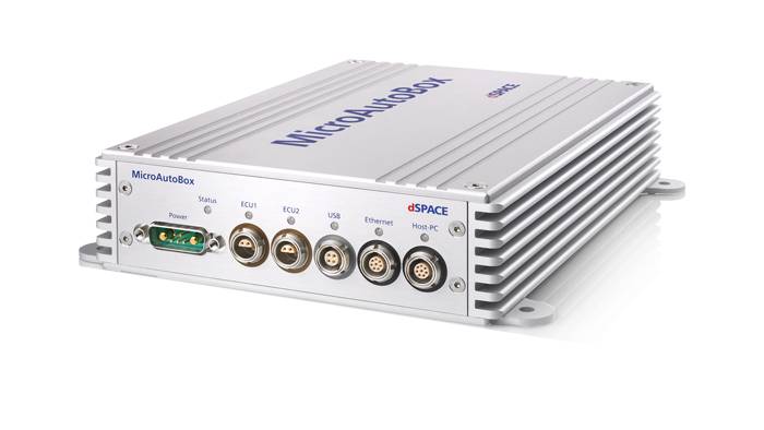
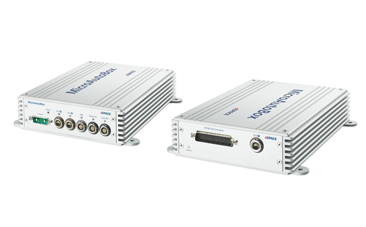
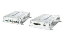
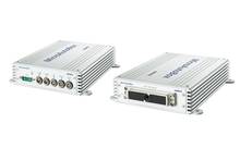
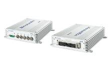
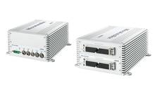
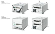
- Robuste, kompakte Bauweise für Prototyping im Fahrzeug
- Umfassende I/O einschließlich CAN-, CAN-FD-, LIN-, K-Line/L-Line-, FlexRay-, Ethernet- und Bypass-Schnittstellen
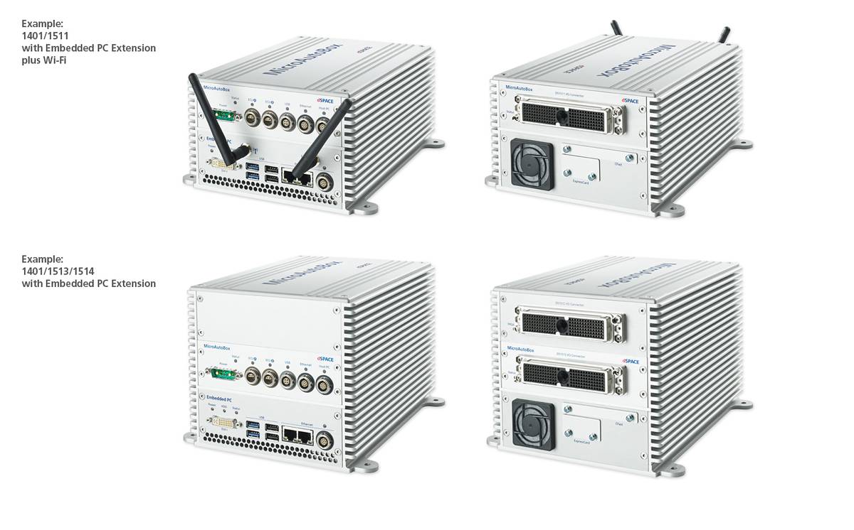
- Varianten mit Simulink®-programmierbarem FPGA und Embedded PC (Windows/Linux)
Anwendungsbereiche
Vorteile
Die besondere Stärke der MicroAutoBox II ist die einzigartige Kombination aus leistungsstarker, umfassender automotiver I/O und extrem kompakter, robuster Bauweise (extreme Schock- und Vibrationstests nach ISO 16750-3:2007). So haben Sie die Möglichkeit, mehrere Fahrzeuge oder eine ganze Testflotte auszustatten, um die Zuverlässigkeit Ihrer Regelfunktionen zu testen. Zusätzlich zur Standard-I/O gibt es die MicroAutoBox II in Varianten mit FPGA-Funktionalität für anwendungsspezifische I/O-Erweiterungen sowie für benutzerprogrammierbare FPGA-Anwendungen. Daneben gibt es MicroAutoBox-II-Varianten mit Schnittstellen zu allen wichtigen automotiven Bussystemen: CAN, CAN FD, LIN, K/L-Line, FlexRay und Ethernet. Wahlweise kann ein zusätzlicher Embedded PC in die MicroAutoBox II integriert werden.
Weitere Leistungsmerkmale
Die MicroAutoBox II kann nach dem Hochfahren autonom starten, mit Boot-Zeiten ähnlich einem Steuergerät. PCs oder Notebooks lassen sich leicht für das Herunterladen von Anwendungen, die Modellparametrierung und die Datenanalyse per Ethernet anschließen (Hot Plugging). Anwendungsprogramme werden im nichtflüchtigen Speicher abgelegt. MicroAutoBox II enthält Signalkonditionierung für automotive Signalpegel und einen integrierten Flight Recorder für Langzeitdatenerfassung (inkl. Unterstützung von USB-Massenspeichergeräten).
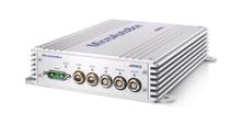
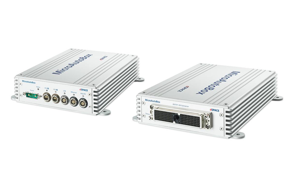
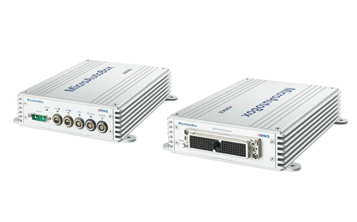
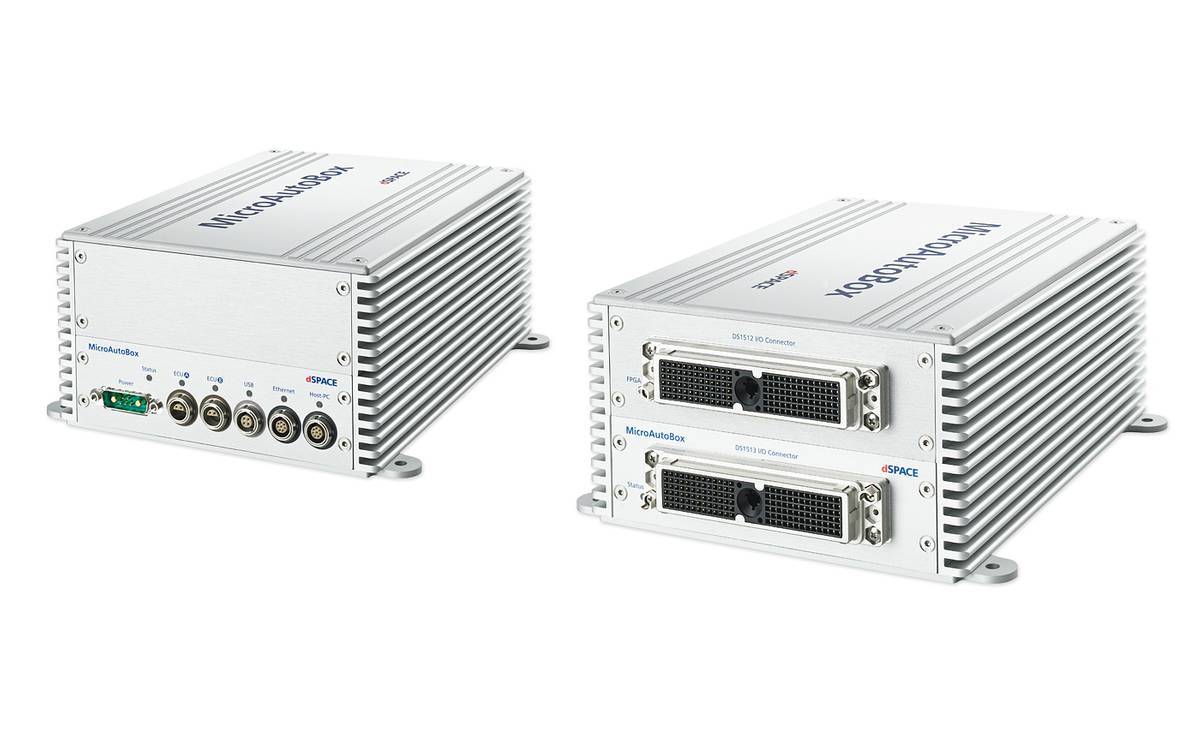
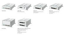
Fünf Standardvarianten
MicroAutoBox II ist in fünf Standardvarianten erhältlich, die sich in Bezug auf Schnittstellen und I/O-Funktionen unterscheiden. Die RapidPro-Hardware stellt mit Standard-Signalkonditionierungs- und Leistungsendstufenmodulen eine optimale Erweiterung zur MicroAutoBox II dar. Alle Standardvarianten können als zusätzlicher Embedded PC integriert werden.
| Parameter | Specification | ||||
|---|---|---|---|---|---|
| MicroAutoBox II | 1401/1507 | 1401/1511 | 1401/1513 | 1401/1511/1514 | 1401/1513/1514 |
| Processor |
|
|
|
|
|
| Memory |
|
|
|
|
|
| Boot time |
|
|
|
|
|
| Interfaces | |||||
|
Host interface |
|
|
|
|
|
|
Ethernet real-time I/O interface |
|
|
|
|
|
|
USB interface |
|
|
|
|
|
|
CAN interface |
|
|
|
|
|
|
Serial interface (based on CAN processor) |
|
|
|
|
|
|
ECU interface |
|
|
|
|
|
|
IP module slot for FlexRay/CAN FD |
|
– | – |
|
|
| Programmable FPGA | – | – | – |
|
|
| Analog input | |||||
|
Resolution |
– |
|
|
|
|
|
Sampling |
– |
|
|
|
|
|
Input voltage range |
– |
|
|
|
|
| Analog output | |||||
|
Resolution |
– |
|
|
|
|
|
Output voltage range |
– |
|
|
|
|
|
Output current |
– |
|
|
|
|
| Digital I/O | |||||
|
General |
– 4) |
|
|
|
|
|
Bit I/O |
– 4) |
|
|
|
|
|
PWM generation / measurement |
– |
|
|
|
|
| Incremental Encoder interfaces | – |
|
|
|
|
| Onboard sensors |
|
|
|
|
|
| Signal conditioning |
|
|
|
|
|
| Physical connections | |||||
| LEMO connectors |
|
|
|
|
|
| Ethernet |
|
|
|
|
|
| Additional connectors |
|
|
|
|
|
| Physical characteristics | |||||
| Enclosure Material |
|
|
|
|
|
| Size |
|
|
|
|
|
| Temperature |
|
|
|
|
|
| Power supply |
|
|
|
|
|
| Power consumption |
|
|
|
|
|
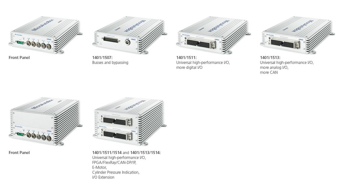
1401/1511/1514, 1401/1513/1514: Universal high-performance I/O, FPGA/FlexRay/CAN-DP/IP, E-Motor, Cylinder Pressure Indication, I/O Extension
Treiben Sie Innovationen voran. Immer am Puls der Technologieentwicklung.
Abonnieren Sie unser Expertenwissen. Lernen Sie von erfolgreichen Projektbeispielen. Bleiben Sie auf dem neuesten Stand der Simulation und Validierung. Jetzt dSPACE direct und dSPACE direct aeropace & defense abonnieren.