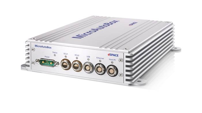
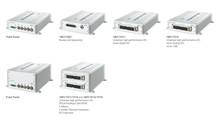
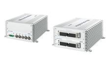
| MicroAutoBox II |
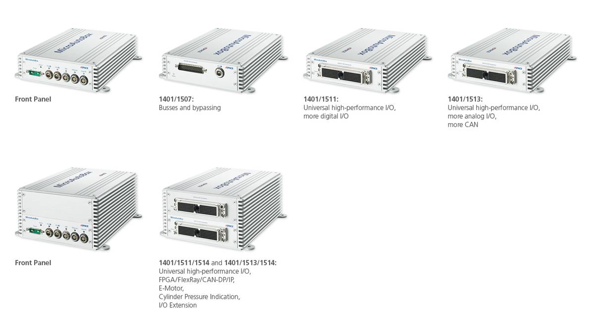
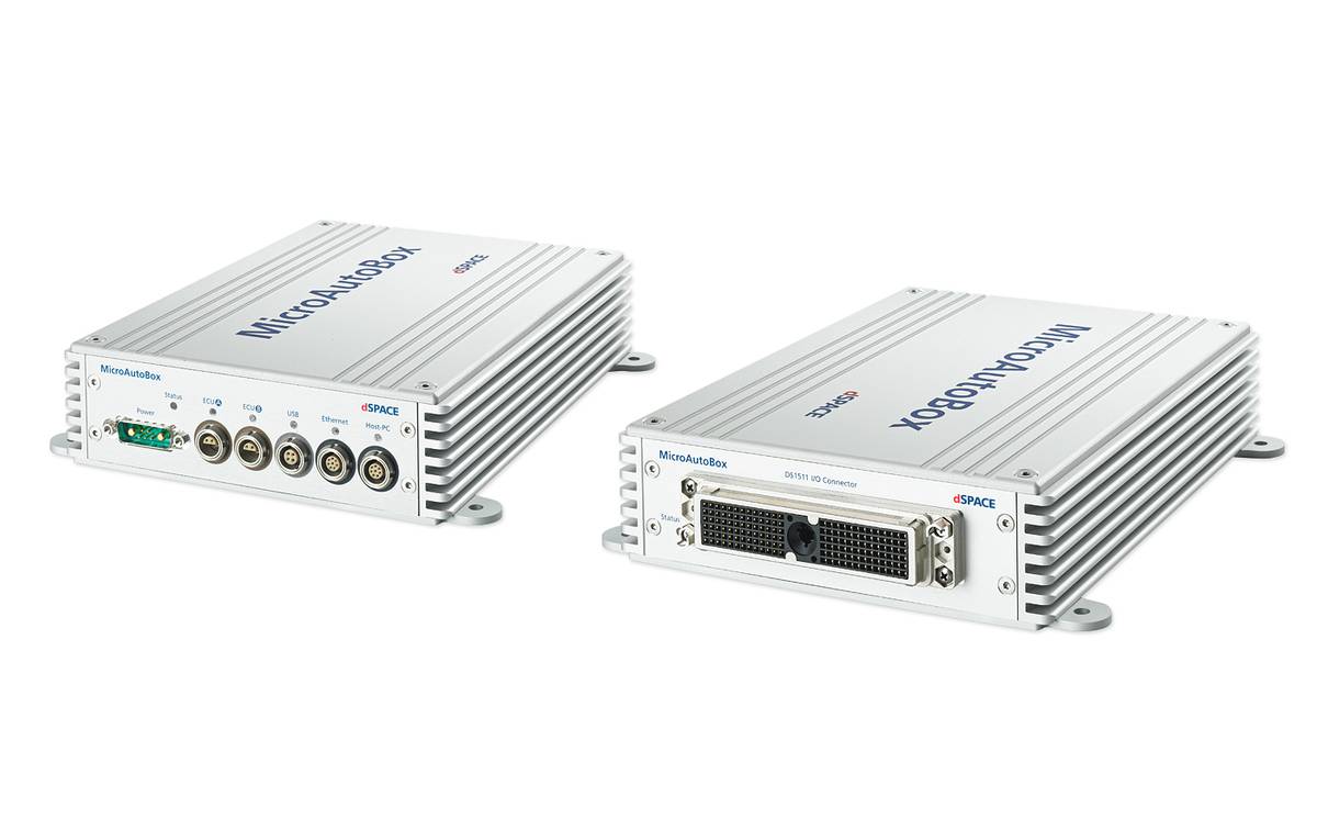
1401/1507 |
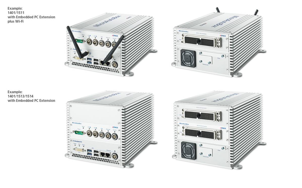
1401/1511 |
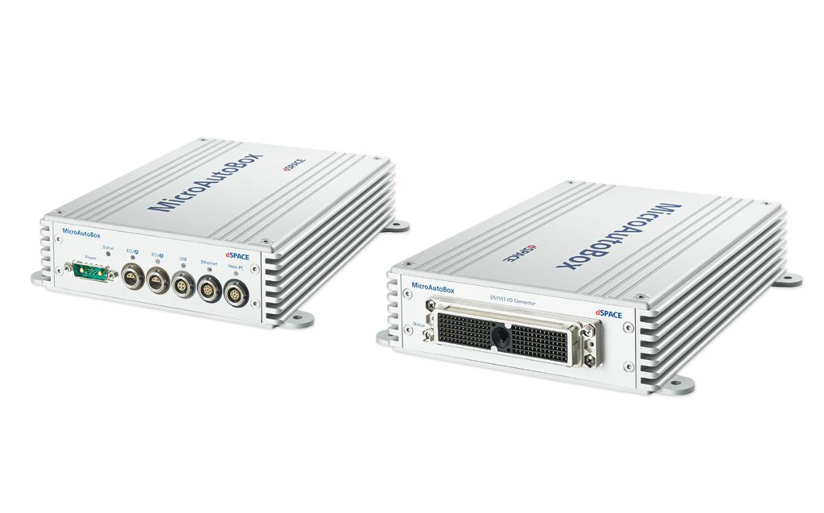
1401/1513 |
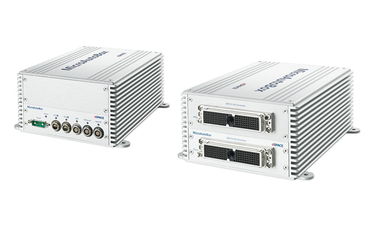
1401/1511/1514 |
1401/1513/1514 |
| Processor |
- IBM PPC 750GL, 900 MHz (incl. 1 MB level 2 cache)
|
- IBM PPC 750GL, 900 MHz (incl. 1 MB level 2 cache)
|
- IBM PPC 750GL, 900 MHz (incl. 1 MB level 2 cache)
|
- IBM PPC 750GL, 900 MHz (incl. 1 MB level 2 cache)
|
- IBM PPC 750GL, 900 MHz (incl. 1 MB level 2 cache)
|
| Memory |
- 16 MB main memory
- 6 MB memory exclusively for communication between MicroAutoBox and PC/notebook
- 16 MB nonvolatile flash memory containing code section and flight data recorder
- Clock/calendar function for time-stamping flight recorder data
|
- 16 MB main memory
- 6 MB memory exclusively for communication between MicroAutoBox and PC/notebook
- 16 MB nonvolatile flash memory containing code section and flight data recorder
- Clock/calendar function for time-stamping flight recorder data
|
- 16 MB main memory
- 6 MB memory exclusively for communication between MicroAutoBox and PC/notebook
- 16 MB nonvolatile flash memory containing code section and flight data recorder
- Clock/calendar function for time-stamping flight recorder data
|
- 16 MB main memory
- 6 MB memory exclusively for communication between MicroAutoBox and PC/notebook
- 16 MB nonvolatile flash memory containing code section and flight data recorder
- Clock/calendar function for time-stamping flight recorder data
|
- 16 MB main memory
- 6 MB memory exclusively for communication between MicroAutoBox and PC/notebook
- 16 MB nonvolatile flash memory containing code section and flight data recorder
- Clock/calendar function for time-stamping flight recorder data
|
| Boot time |
- Depending on flash application size. Measurement examples:
- 1 MB application: 160 ms
- 3 MB application: 340 ms
|
- Depending on flash application size. Measurement examples:
- 1 MB application: 160 ms
- 3 MB application: 340 ms
|
- Depending on flash application size. Measurement examples:
- 1 MB application: 160 ms
- 3 MB application: 340 ms
|
- Depending on flash application size. Measurement examples:
- 1 MB application: 160 ms
- 3 MB application: 340 ms
|
- Depending on flash application size. Measurement examples:
- 1 MB application: 160 ms
- 3 MB application: 340 ms
|
| Interfaces |
|
|
|
|
|
|
Host interface
|
- 100/1000 Mbit/s Ethernet connection (TCP/IP)
- Fully compatible with standard network infrastructure
- LEMO connector
- Optional XCP on Ethernet interface to support third-party calibration and measurement tools
|
- 100/1000 Mbit/s Ethernet connection (TCP/IP)
- Fully compatible with standard network infrastructure
- LEMO connector
- Optional XCP on Ethernet interface to support third-party calibration and measurement tools
|
- 100/1000 Mbit/s Ethernet connection (TCP/IP)
- Fully compatible with standard network infrastructure
- LEMO connector
- Optional XCP on Ethernet interface to support third-party calibration and measurement tools
|
- 100/1000 Mbit/s Ethernet connection (TCP/IP)
- Fully compatible with standard network infrastructure
- LEMO connector
- Optional XCP on Ethernet interface to support third-party calibration and measurement tools
|
- 100/1000 Mbit/s Ethernet connection (TCP/IP)
- Fully compatible with standard network infrastructure
- LEMO connector
- Optional XCP on Ethernet interface to support third-party calibration and measurement tools
|
|
Ethernet real-time I/O interface
|
- 100/1000 Mbit/s Ethernet connection (UDP/IPTCP/IP on request)
- RTI Ethernet (UDP) Blockset (optional) for read/write access
- LEMO connector
|
- 100/1000 Mbit/s Ethernet connection (UDP/IPTCP/IP on request)
- RTI Ethernet (UDP) Blockset (optional) for read/write access
- LEMO connector
|
- 100/1000 Mbit/s Ethernet connection (UDP/IPTCP/IP on request)
- RTI Ethernet (UDP) Blockset (optional) for read/write access
- LEMO connector
|
- 100/1000 Mbit/s Ethernet connection (UDP/IPTCP/IP on request)
- RTI Ethernet (UDP) Blockset (optional) for read/write access
- LEMO connector
|
- 100/1000 Mbit/s Ethernet connection (UDP/IPTCP/IP on request)
- RTI Ethernet (UDP) Blockset (optional) for read/write access
- LEMO connector
|
|
USB interface
|
- USB 2.0 interface for long-term data acquisition with USB mass storage devices
- LEMO connector
|
- USB 2.0 interface for long-term data acquisition with USB mass storage devices
- LEMO connector
|
- USB 2.0 interface for long-term data acquisition with USB mass storage devices
- LEMO connector
|
- USB 2.0 interface for long-term data acquisition with USB mass storage devices
- LEMO connector
|
- USB 2.0 interface for long-term data acquisition with USB mass storage devices
- LEMO connector
|
|
CAN interface
|
|
|
- 6 CAN channels (partial networking supported)
|
|
- 6 CAN channels (partial networking supported)
|
|
Serial interface (based on CAN processor)
|
- 2 x RS232 interface
- 2 x serial interface usable as K/L-Line or LIN interface
|
- 2 x RS232 interface
- 2 x serial interface usable as K/L-Line or LIN interface
|
- 3 x RS232 interface
- 3 x serial interface usable as K/L-Line or LIN interface
|
- 2 x RS232 interface
- 2 x serial interface usable as K/L-Line or LIN interface
|
- 3 x RS232 interface
- 3 x serial interface usable as K/L-Line or LIN interface
|
|
ECU interface
|
- 3 x dual-port memory interface
|
- 2 x dual-port memory interface
|
- 2 x dual-port memory interface
|
- 2 x dual-port memory interface
|
- 2 x dual-port memory interface
|
|
IP module slot for FlexRay/CAN FD
|
- 2 slots1) for FlexRay2) or CAN FD modules
|
– |
– |
- 2 slots1) for FlexRay2) or CAN FD modules
|
- 2 slots1) for FlexRay2) or CAN FD modules
|
| Programmable FPGA |
– |
– |
– |
- Xilinx® Kintex®-7 (XC7K325T)
|
- Xilinx® Kintex®-7 (XC7K325T)
|
| Analog input |
|
|
|
|
|
|
Resolution
|
– |
|
|
|
|
|
Sampling
|
– |
- 16 parallel channels with 1 Msps conversion rate
|
|
- 16 parallel channels with 1 Msps conversion rate
|
|
|
Input voltage range
|
– |
|
|
|
|
| Analog output |
|
|
|
|
|
|
Resolution
|
– |
|
|
|
|
|
Output voltage range
|
– |
|
|
|
|
|
Output current
|
– |
|
|
|
|
| Digital I/O |
|
|
|
|
|
|
General
|
– 4) |
- FPGA-based digital I/O
- RTI software support for bit I/O, frequency, and PWM generation/measurements
|
- FPGA-based digital I/O
- RTI software support for bit I/O, frequency, and PWM generation/measurements
|
- FPGA-based digital I/O
- RTI software support for bit I/O, frequency, and PWM generation/measurements
|
- FPGA-based digital I/O
- RTI software support for bit I/O, frequency, and PWM generation/measurements
|
|
Bit I/O
|
– 4) |
- 40 inputs
- 40 outputs, 5 mA output current
- Input/output logic levels: 5 V or levels up to 40 V (depending on VDrive), selectable
|
|
- 40 inputs3)
- 40 outputs, 5 mA output current3)
- Input/output logic levels: 5 V or levels up to 40 V (depending on VDrive), selectable
|
- 24 inputs3)
- 24 outputs, 5 mA output current3)
- Input/output logic levels: 5 V or levels up to 40 V (depending on VDrive), selectable
|
|
PWM generation / measurement
|
– |
- All channels fully configurable as frequency or PWM inputs/outputs
- PWM frequency 0.0003 Hz ... 150 KHz, duty cycle 0 ... 100%, up to 21-bit resolution
|
- All channels fully configurable as frequency or PWM inputs/outputs
- PWM frequency 0.0003 Hz ... 150 KHz, duty cycle 0 ... 100%, up to 21-bit resolution
|
- All channels fully configurable as frequency or PWM inputs/outputs
- PWM frequency 0.0003 Hz ... 150 KHz, duty cycle 0 ... 100%, up to 21-bit resolution
|
- All channels fully configurable as frequency or PWM inputs/outputs
- PWM frequency 0.0003 Hz ... 150 KHz, duty cycle 0 ... 100%, up to 21-bit resolution
|
| Incremental Encoder interfaces |
– |
- 4 x Encoder interfaces with index support3)
- Position Count range -2,097,152.0 ... +2,097,151.75 (-221 ... +221-0.25)
- Configurable noise filter
|
- 4 x Encoder interfaces with index support3)
- Position Count range -2,097,152.0 ... +2,097,151.75 (-221 ... +221-0.25)
- Configurable noise filter
|
- 4 x Encoder interfaces with index support3)
- Position Count range -2,097,152.0 ... +2,097,151.75 (-221 ... +221-0.25)
- Configurable noise filter
|
- 4 x Encoder interfaces with index support3)
- Position Count range -2,097,152.0 ... +2,097,151.75 (-221 ... +221-0.25)
- Configurable noise filter
|
| Onboard sensors |
- Motion sensing with 3-axis accelerometer.
- Pressure sensing for altitude indication.
|
- Motion sensing with 3-axis accelerometer.
- Pressure sensing for altitude indication.
|
- Motion sensing with 3-axis accelerometer.
- Pressure sensing for altitude indication.
|
- Motion sensing with 3-axis accelerometer.
- Pressure sensing for altitude indication.
|
- Motion sensing with 3-axis accelerometer.
- Pressure sensing for altitude indication.
|
| Signal conditioning |
- Signal conditioning for automotive signal levels, no power driver included
- Overvoltage protection; overcurrent and short circuit protection
|
- Signal conditioning for automotive signal levels, no power driver included
- Overvoltage protection; overcurrent and short circuit protection
|
- Signal conditioning for automotive signal levels, no power driver included
- Overvoltage protection; overcurrent and short circuit protection
|
- Signal conditioning for automotive signal levels, no power driver included
- Overvoltage protection; overcurrent and short circuit protection
|
- Signal conditioning for automotive signal levels, no power driver included
- Overvoltage protection; overcurrent and short circuit protection
|
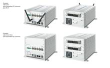
| Physical connections |
|
|
|
|
|
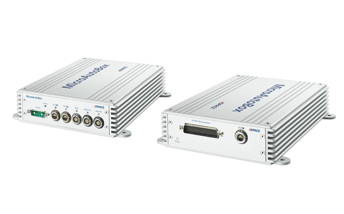
| LEMO connectors |
- for 2 ECU interfaces, Ethernet I/O interface, USB interface, and Ethernet host interface
|
- for 2 ECU interfaces, Ethernet I/O interface, USB interface, and Ethernet host interface
|
- for 2 ECU interfaces, Ethernet I/O interface, USB interface, and Ethernet host interface
|
- for 2 ECU interfaces, Ethernet I/O interface, USB interface, and Ethernet host interface
|
- for 2 ECU interfaces, Ethernet I/O interface, USB interface, and Ethernet host interface
|
| Ethernet |
- Host interface (100/1000 Mbit/s, TCP/IP) for notebook/PC connection (for program load, experiment configuration, signal monitoring, and flight recorder read-out)
- Integrated Ethernet switch
|
- Host interface (100/1000 Mbit/s, TCP/IP) for notebook/PC connection (for program load, experiment configuration, signal monitoring, and flight recorder read-out)
- Integrated Ethernet switch
|
- Host interface (100/1000 Mbit/s, TCP/IP) for notebook/PC connection (for program load, experiment configuration, signal monitoring, and flight recorder read-out)
- Integrated Ethernet switch
|
- Host interface (100/1000 Mbit/s, TCP/IP) for notebook/PC connection (for program load, experiment configuration, signal monitoring, and flight recorder read-out)
- Integrated Ethernet switch
|
- Host interface (100/1000 Mbit/s, TCP/IP) for notebook/PC connection (for program load, experiment configuration, signal monitoring, and flight recorder read-out)
- Integrated Ethernet switch
|
| Additional connectors |
|
- ZIF connector for I/O signals, mechanically secured, Sub-D connector for power supply
|
- ZIF connector for I/O signals, mechanically secured, Sub-D connector for power supply
|
- ZIF connector for I/O signals, mechanically secured, Sub-D connector for power supply
|
- ZIF connector for I/O signals, mechanically secured, Sub-D connector for power supply
|
| Physical characteristics |
|
|
|
|
|
| Enclosure Material |
|
|
|
|
|
| Size |
- Approx. 200 x 225 x 50 mm (7.9 x 8.9 x 2.0 in)
|
- Approx. 200 x 225 x 50 mm (7.9 x 8.9 x 2.0 in)
|
- Approx. 200 x 225 x 50 mm (7.9 x 8.9 x 2.0 in)
|
- Approx. 200 x 225 x 95 mm (7.9 x 8.9 x 3.8 in)
|
- Approx. 200 x 225 x 95 mm (7.9 x 8.9 x 3.8 in)
|
| Temperature |
- Operating (case) temperature: -40 ... +85 °C (-40 ... +185 °F)
- Storage temperature: -55 ... +125 °C (-67 ... +257 °F)
|
- Operating (case) temperature: -40 ... +85 °C (-40 ... +185 °F)
- Storage temperature: -55 ... +125 °C (-67 ... +257 °F)
|
- Operating (case) temperature: -40 ... +85 °C (-40 ... +185 °F)
- Storage temperature: -55 ... +125 °C (-67 ... +257 °F)
|
- Operating (case) temperature: -40 ... +85 °C (-40 ... +185 °F)
- Storage temperature: -55 ... +125 °C (-67 ... +257 °F)
|
- Operating (case) temperature: -40 ... +85 °C (-40 ... +185 °F)
- Storage temperature: -55 ... +125 °C (-67 ... +257 °F)
|
| Power supply |
- 6 ... 40 V input power supply, protected against overvoltage and reverse polarity
|
- 6 ... 40 V input power supply, protected against overvoltage and reverse polarity
|
- 6 ... 40 V input power supply, protected against overvoltage and reverse polarity
|
- 6 ... 40 V input power supply, protected against overvoltage and reverse polarity
|
- 6 ... 40 V input power supply, protected against overvoltage and reverse polarity
|
| Power consumption |
|
|
|
|
|