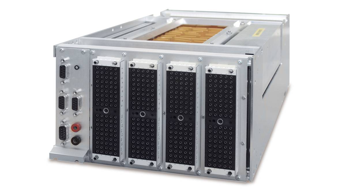
DS2680 I/O 单元

适用于动力传动系统及车辆动力学场景的 MultiCompact I/O 单元

DS2680 I/O 单元是SCALEXIO 系统的 MultiCompact I/O单元,可以提供变速箱或车辆动力学 ECU 的硬件在环仿真所需的所有 I/O 通道。

应用领域

DS2680 I/O Unit是SCALEXIO 系统的 MultiCompact 单元,可以提供变速箱或车辆动力学 ECU 的硬件在环仿真所需的所有 I/O 通道。大多数 I/O 通道都有一个固定功能,即都有专用的模拟通道或数字通道。

主要优点

尽管设计紧凑,DS2680提供了大量的预定义通道,这些通道包含了FIU功能。DS2680具有如此卓越的功能,并且性价比高,因此成为了具体应用场景的理想工具。

组件变体

DS2680 可以带有集成总线板。集成总线板卡为LIN、CAN 及 FlexRay 总线协议分别提供了两个通道。如果您需要更多的或不同的总线通道,比如需要四个 CAN 通道,您可以选择 HighFlex 总线板卡作为替代组件或附加扩展。

I/O 功能

DS2680提供38个I/O功能,这些功能由不同的I/O通道支持。所有通道都在dSPACE ConfigurationDesk软件中以图形化的方式进行定义和配置。

模拟输入:

  • 电压:
  • 电压信号捕获
  • 输入电流
  • 触发电流输入
  • 电流信号捕获

模拟输出:

  • 电压输出
  • 电流吸收器
  • 波表电压输出
  • 波表电流吸收器
  • 波形电压输出
  • 波形电流吸收器
  • 角度波表数字输出

数字输入

  • 多位输入
  • 触发器输入
  • PWM/PFM 输入
  • 数字脉冲捕获
  • 馈入

数字输出

  • 多位输出
  • PWM/PFM 输出
  • 数字脉冲输出
  • 波表数字输出
  • 波形数字输出
  • 波表数字输出
  • 馈出

发动机仿真

  • 注入/点火电压输入
  • 注入/点火电流输入
  • 曲轴/凸轮电压输出
  • 曲轴/凸轮电流吸收器
  • 曲轴/凸轮数字输出
  • 爆震信号输出
  • 氧DCR
  • 氧NCCR

电阻仿真

  • 电阻输出
  • 电位器输出

深度传感器仿真

  • 数字增量式编码器输出
  • 轮速输出

电气故障测试

DS2680 含有一个FIU,能在在故障出现时测试 ECU 的行为,其可以作为 SCALEXIO 系统的中央 FIU。每个通道都有一个故障路由单元 (FRU),其通过故障轨道对FIU进行断开或连接。

真实负载

需要时,可将替代负载插到 DS2680系统内部。这种情况下,可通过可更换式负载板卡安装不同的插接负载。真实负载或大型替代负载可以通过随附的负载接头进行外部连接。

Parameters Specification
Signal measurement
  • Max. 6 A per channel
  • Substitute loads pluggable, up to 2 W per measurement channel
  • Connector for real loads
  • Channel bundling to increase current carrying capacity
  • Multifuse for electrical safety
  • 20 analog inputs
    (Analog In 1)
    • Only voltage measurement
    • Measurement range 0 ... 60 V
    • Resolution 16 bit
  • 30 digital inputs
    (Digital In 1)
    • Voltage measurement
    • Trigger value 0 ... 24 V
    • Voltage range 0 ... 60 V
  • 18 variable inputs
    (Flexible In 2)
    • Voltage measurement digital
      • Voltage range 0 ... 60 V
      • Trigger value 0 ... 24 V
    • Current measurement analog and digital
      • Measurement range ±18 A
      • Resolution 16 bit (analog)
Signal generation
  • 15 analog outputs (DC)
    (Analog Out 1)
    • Only voltage generation
    • Output voltage 0 ... 10 V
    • Output current -5 ... +5 mA
    • Resolution 14 bit
  • 8 analog outputs (DC)
    (Analog Out 4)
    • Output voltage 0 ... 10 V
    • Output current -5 ... +5 mA
    • Resolution 14 bit
    • Current sink: Current range -30 ... +30 mA
  • 7 analog outputs (AC) (Analog Out 3)
    • Only voltage generation
    • Output voltage -20 ... +20 V
    • Resolution 14 bit
    • Effective inner resistance 250 Ω
  • 12 resistance simulation channels (Resistance Out 1)
    • Resistance range 16 Ω ... 1 MΩ
    • Voltage range -3 ... +18 V to GND
    • Current range -80 ... +80 mA
    • Power max. 250 mW
  • 28 digital outputs (Digital Out 1)
    • Configurable as low-side/high-side switch or push/pull
    • Low-side = GND
    • High-Side = VBAT or Dig-Out-Ref
    • High-side voltage range: 5 ... 60 V
    • Current range -80 ... +80 mA
Special I/O channels
  • 2 analog input and output groups, e.g., for lambda probe simulation (Analog In 2, Analog Out 2, Load 1)
    • 1 ADC
    • 1 DAC
    • 1 load (component channel)
    • Voltage range -10 ... +10 V
    • Current range -5 ... +5 mA
Voltage supply
  • 1 channel to control the power unit (Power Control 1)
    • Control of TDK-Lambda Genesys™ power supply
  • 6 power switches without current measurement (Power Switch 2)
    • Up to 60 V
    • Continuous current 4 x 6 A per channel (but a maximum total of 50 A for all channels)
Buses (Only for DS2680 with bus support)
  • 2 CAN (CAN 1)
    • CAN/CAN FD (ISO 11898-1, ISO 11898-5, ISO 11898-6, and non-ISO)
    • High-speed CAN (ISO 11898-2)
    • Fault-tolerant CAN (ISO 11898-3)
    • J1939
    • Software-switchable bus termination
    • Conventional CAN VBAT
  • 2 LIN (LIN 1)
    • Configurable as K-Line
    • Conventional LIN VBAT
    • Software-switchable bus termination
  • 2 FlexRay (FlexRay 1)
    • Only 4 bus lines, i.e., 1 fault-tolerant FlexRay bus (channels A + B) or 2 FlexRay buses (channel A)
    • Conventional FlexRay VBAT
Failure Insertion Unit
  • General
    • Voltage ±60 V
    • Fault switch for up to 48 A
    • Continuous current for high-current failrail 48 A
    • Continuous current failrail with low capacitance 1 A
  • Fault types
    • Broken wire
    • Short circuit to GND or UBAT
    • Crossed wire between two channels
    • All faults with optional bouncing
Internal communication interface
  • IOCNET
Physical size
  • 475 x 215 x 132 mm (18.7 x 8.5 x 5.2 in)
Voltage supply
  • 24 V
Typical power consumption
  • 84 W including buses
  • 60 W without buses

  • SCALEXIO 产品信息, PDF, 英語, 16194 KB
Product Information Support Contact Information

推动创新进程。我们始终在技术开发的最前沿。

欢迎订阅我们简讯,了解我们的专业技术以及产品。希望我们的成功案例能够对您有所帮助。快速了解仿真和验证的最新信息。欢迎订阅/管理dSPACE简讯和dSPACE航空速报。

Enable form call

At this point, an input form from Click Dimensions is integrated. This enables us to process your newsletter subscription. The form is currently hidden due to your privacy settings for our website.

External input form

By activating the input form, you consent to personal data being transmitted to Click Dimensions within the EU, in the USA, Canada or Australia. More on this in our privacy policy.