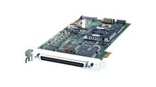
DS1104 R&D Controller Board
Cost-effective single-board system for controller development
The DS1104 R&D Controller Board upgrades a PC to a development system for rapid control prototyping. The board can be installed in virtually any PC with a free PCI or PCIe slot.
- Cost-effective entry system
- Real-time processor and comprehensive I/O on a single board
- PCI or PCIe (PCI Express) host interface for use in PCs

Application Areas
The real-time hardware based on PowerPC technology and its set of I/O interfaces make the controller board an ideal solution for developing controllers in various fields, such as drives, robotics, and aerospace. The board is used in many university laboratories.
Key Benefits
The DS1104 R&D Controller Board is a cost-effective entry-level system with I/O interfaces and a real-time processor on a single board that can be plugged directly into a PC. It upgrades your PC to a development tool for rapid control prototyping and is ideal for developing smaller control applications or for education purposes. Real-Time Interface (RTI) provides Simulink® blocks for graphical I/O configuration. The board can be installed in virtually any PC with a free PCI or PCIe slot.
Using Real-Time Interface
With Real-Time Interface (RTI), you can easily run your function models on the DS1104 R&D Controller Board. You can configure all I/O graphically, insert the blocks into a Simulink block diagram, and generate the model code via Simulink® Coder™. The real-time model is compiled, downloaded, and started automatically. This reduces the implementation time to a minimum.
| Parameter | Specification | |
|---|---|---|
| Processor |
|
|
| Memory | Global Memory |
|
| Flash memory |
|
|
| Timer | 4 general-purpose timers |
|
| 1 sampling rate dimer (decrementer) |
|
|
| 1 time base counter |
|
|
| Interrupt controller |
|
|
| A/D converter | Channels |
|
| Resolution |
|
|
| Input voltage range |
|
|
| Conversion time |
|
|
| Offset error |
|
|
| Gain error |
|
|
| Offset drift |
|
|
| Gain drift |
|
|
| Signal-to-noise ratio |
|
|
| D/A converter | Channels |
|
| Resolution |
|
|
| Output range |
|
|
| Settling time |
|
|
| Offset error |
|
|
| Gain error |
|
|
| Offset drift |
|
|
| Gain drift |
|
|
| Signal-to-noise ratio |
|
|
| Imax |
|
|
| Digital I/O | Channels |
|
| Voltage range |
|
|
| Iout, max |
|
|
1) Speed and timing specifications describe the capabilities of the hardware components and circuits of our products. Depending on the software complexity, the attainable overall performance figures can deviate significantly from the hardware specifications.
| Parameter | Specification | ||
|---|---|---|---|
| Digital incremental encoder interface | Channels |
|
|
| Position Counters |
|
||
| sensor supply voltage |
|
||
| Serial interface | Configuration |
|
|
| Baud rate |
|
||
| Slave DSP | Type |
|
|
| Clock rate |
|
||
| Memory |
|
||
| I/O channels 1) |
|
||
| Input voltage range |
|
||
| Output current |
|
||
| Host interface (requires one PCI or one PCIe x 1 slot) | PCI | PCIe | |
| Physical characteristics | Physical size |
|
|
| Ambient temperature |
|
|
|
| Cooling |
|
|
|
| Power consumption |
|
Please inquire | |
| Power supply |
|
Please inquire | |
1) The exact number of I/O channels depends on your configuration and is described in the user documentation.
혁신을 추진하세요. 항상 기술 개발의 동향을 주시해야 합니다.
저희 전문 지식 서비스에 가입하세요. dSPACE의 성공적인 프로젝트 사례를 확인해 보세요. 시뮬레이션 및 검증에 대한 최신 정보를 받아보세요. 지금 바로 dSPACE 다이렉트(뉴스레터)를 구독하세요.