SCALEXIO EMH Solution dédiée à la simulation de moteurs électriques
Simulation de moteurs électriques sur plate-forme processeur
La solution SCALEXIO EMH Solution fournit une bibliothèque d’E/S complète pour ConfigurationDesk, dédiée à la simulation HIL de moteurs électriques, sur plate-forme processeur.
- Simulation sur plate-forme processeur
- Blocs fonctionnels prédéfinis
- Idéal pour des applications PWM et PSS
La solution SCALEXIO EMH Solution facilite la simulation de moteurs électriques sur plate-forme processeur.

Simulation de moteurs électriques sur plate-forme processeur
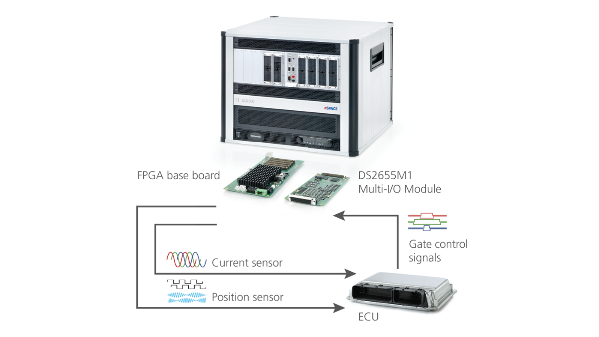
La solution SCALEXIO EMH Solution peut être utilisée pour implémenter les fonctions d’E/S afin de simuler jusqu’à deux moteurs électriques. Pour cela, la carte FPGA nécessaire (DS6601, DS6602, ou DS2655) est configurée depuis ConfigurationDesk. Grâce aux blocs de fonctions prédéfinies, les utilisateurs n’ont pas besoin de programmer ou de générer du code FPGA. Le module DS2655M1 Multi-I/O Module et les unités de calcul angulaire intégrées (APUs) permettent d’utiliser des E/S hautes résolutions pour supporter des applications dans les domaines de la simulation des capteurs de position (PSS) et de modulation de largeur d’impulsion (PWM). L’attribution variable des voies d’E/S et le support flexible jusqu’à cinq modules DS2655M1 Multi-I/O Module déploient entièrement le potentiel du matériel. Quand un contrôleur de moteur nécessite une résolution de simulation supérieure, il est possible de passer directement à une simulation sur FPGA sans avoir à modifier le système.
La conception de la solution EMH Solution FPGA intègre quatre APUs internes tournant sur la carte FPGA pour le calcul de la position locale. De plus, grâce à la technologie IOCNET, il est possible de référencer jusqu’à 6 APUs maîtres en tant que générateurs de position. Chaque capteur de position peut être configuré pour utiliser un des dix APUs comme générateur de position.
Le nombre de voies d’E/S disponibles varie selon le nombre de modules DS2655M1.
Principales fonctions pour la simulation des capteurs de position (PSS)
| Function | Description | I/O Requirements per Function | |
|---|---|---|---|
| Resolver Out | Simulation with configurable pole pair number, offset angle, transformer ratio. Excitation input signal delay. Output amplitude and phase error manipulation. | 2 |
Excitation: 1x Analog In Sin/Cos: 2x Analog Out |
| Sine Encoder Out | Simulation with configurable number of lines, output amplitude and DC offset | 2 | A,B, Index: 3x Analog Out Or1 6x Analog Out |
| Incremental Encoder Out | Simulation with configurable number of lines and offset angle | 2 | A,B, Index: 3x Digital (Out) Or1 6x Digital (Out) |
| Hall Encoder Out | Simulation with configurable pole pair number, offset angle, angle-dependent pulse activation/deactivation | 2 | A,B,C: 3x Digital (Out) Or1 6x Digital (Out) |
| Analog Wavetable Encoder Out | Output with freely designable analog shape format for 360 degrees with up to 16383 values and optional linear interpolation for intermediate values. Configurable number of waveforms per revolution. | 3 | 1x Analog Out |
|
Digital Wavetable Encoder Out |
Output with freely designable digital shape format for 360 degrees with up to 16383 values. Configurable number of waveforms per revolution. | 3 | 1x Digital (Out) |
Principales fonctions pour la modulation de largeur d’impulsion (PWM)
| Function | Description | I/O Requirements per Function | |
|---|---|---|---|
| Six-Channel PWM In | Supporting duty cycle, period time, latch time and dead time2 measurement and configurable interrupt generation (latch-based measurement), oversampling, downsampling Optional external triggering Optional2 dead time violation interrupt generation | 2 |
Gates: 3x Digital (In) Or2 Optional ext. trigger: Optional latch pulse: 1x Digital (Out) |
| Single-Channel PWM In | Combined edge-based and latch-based measurement of duty cycle and frequency | 4 | 1x Digital (In) |
| Single-Channel PWM Out | PWM generation with variable frequency and duty cycle | 4 | 1x Digital (Out) |
Fonctions d’E/S de base
| Function | Description | Number of Functions per FPGA Base Board | I/O Requirements per Function |
|---|---|---|---|
| Multi-Bit In | Standard digital input functionality for variable number of channels | 4 | 1-50 Digital (In) |
| Multi-Bit Out | Standard digital output functionality for variable number of channels | 4 | 1-50 Digital (Out) |
| Multi-Voltage In | Standard analog input functionality for variable number of channels | 4 | 1-25 Analog In |
| Multi-Voltage Out | Standard analog output functionality for variable number of channels | 4 | 1-25 Analog Out |
-
- Afficher en ligne
- Téléchargement
- SCALEXIO Système temps réel modulaire pour les applications RCP et HIL
- ASM Electric Components Modèles temps réel pour la simulation de moteurs et de systèmes électriques automobiles
- Package de simulation Electrical Power Systems Simulation temps réel simple de circuits d’électronique de puissance développés avec Simscape Electrical™ (Specialized Power Systems)
- Ventes Notre équipe d’ingénieurs d’affaires vous assistera dans le choix de votre système dSPACE. Ils vous fourniront également les tarifs et toutes les informations souhaitées concernant d’autres produits dSPACE.
- Achat de logiciels dSPACE Informations sur le téléchargement, l’installation et le système de licence des logiciels dSPACE
Faire avancer l'innovation. Toujours à la pointe de l'évolution technologique.
S’abonner à nos newsletters, gérer ses abonnements ou se désabonner. La newsletter mensuelle contenant toutes les informations liées à l’aéronautique et défense.